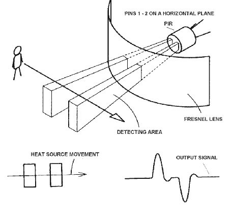
PIR sensors are more complicated than many of the other sensors explained in these tutorials (like photocells, FSRs and tilt switches) because there are multiple variables that affect the sensors input and output. To begin explaining how a basic sensor works, we'll use this rather nice diagram (if anyone knows where it originates plz let me know).
The PIR sensor itself has two slots in it, each slot is made of a special material that is sensitive to IR. The lens used here is not really doing much and so we see that the two slots can 'see' out past some distance (basically the sensitivity of the sensor). When the sensor is idle, both slots detect the same amount of IR, the ambient amount radiated from the room or walls or outdoors. When a warm body like a human or animal passes by, it first intercepts one half of the PIR sensor, which causes a positive differential change between the two halves. When the warm body leaves the sensing area, the reverse happens, whereby the sensor generates a negative differential change. These change pulses are what is detected.
The PIR Sensor
The IR sensor itself is housed in a hermetically sealed metal can to improve noise/temperature/humidity immunity. There is a window made of IR-transmissive material (typically coated silicon since that is very easy to come by) that protects the sensing element. Behind the window are the two balanced sensors.
You can see above the diagram showing the element window, the two pieces of sensing material
This image shows the internal schematic. There is actually a JFET inside (a type of transistor) which is very low-noise and buffers the extremely high impedence of the sensors into something a low-cost chip (like the BIS0001) can sense.
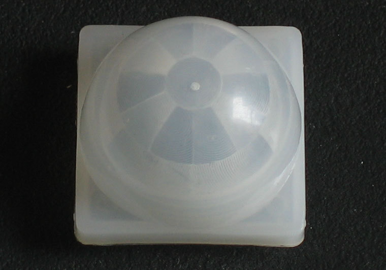
Lenses
PIR sensors are rather generic and for the most part vary only in price and sensitivity. Most of the real magic happens with the optics. This is a pretty good idea for manufacturing: the PIR sensor and circuitry is fixed and costs a few dollars. The lens costs only a few cents and can change the breadth, range, sensing pattern, very easily.In the diagram up top, the lens is just a piece of plastic, but that means that the detection area is just two rectangles. Usually we'd like to have a detection area that is much larger. To do that, we use a simple lens such as those found in a camera: they condenses a large area (such as a landscape) into a small one (on film or a CCD sensor). For reasons that will be apparent soon, we would like to make the PIR lenses small and thin and moldable from cheap plastic, even though it may add distortion. For this reason the sensors are actually Fresnel lenses:
The Fresnel lens condenses light, providing a larger range of IR to the sensor.
OK, so now we have a much larger range. However, remember that we actually have two sensors, and more importantly we dont want two really big sensing-area rectangles, but rather a scattering of multiple small areas. So what we do is split up the lens into multiple section, each section of which is a fresnel lens.
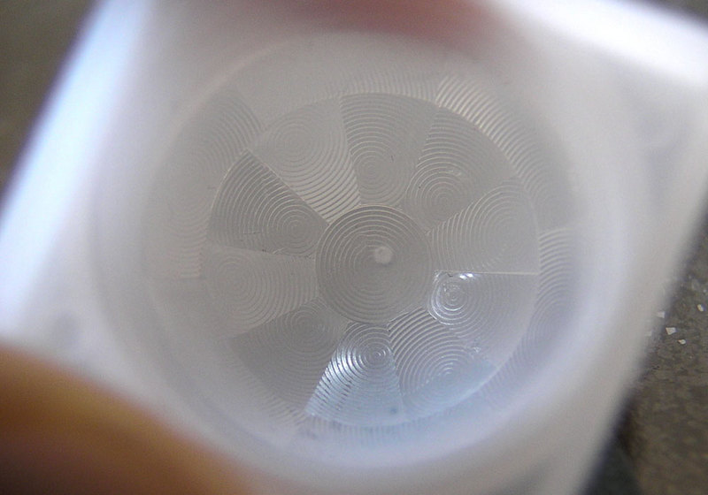
This macro shot shows the different Frenel lenses in each facet!
The different faceting and sub-lenses create a range of detection areas, interleaved with each other. Thats why the lens centers in the facets above are 'inconsistant' - every other one points to a different half of the PIR sensing element
Here is another image, more qualitative but not as quantitative. (Note that the sensor in the Adafruit shop is 110° not 90°)