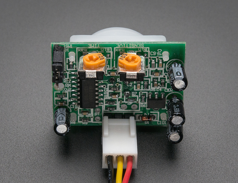
Most PIR modules have a 3-pin connection at the side or bottom. The pinout may vary between modules so triple-check the pinout! It's often silkscreened on right next to the connection (at least, ours is!) One pin will be ground, another will be signal and the final one will be power. Power is usually 3-5VDC input but may be as high as 12V. Sometimes larger modules don't have direct output and instead just operate a relay in which case there is ground, power and the two switch connections.
The output of some relays may be 'open collector' - that means it requires a pullup resistor. If you're not getting a variable output be sure to try attaching a 10K pullup between the signal and power pins.
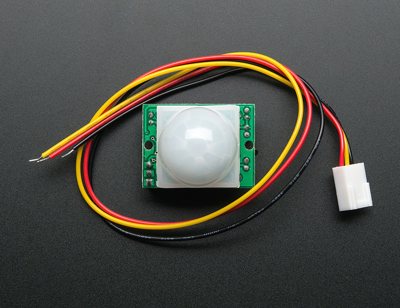
An easy way of prototyping with PIR sensors is to connect it to a breadboard since the connection port is 0.1" spacing. Some PIRs come with header on them already, the one's from adafruit have a straight 3-pin header on them for connecting a cable