|
Parallel cables pinout and port info
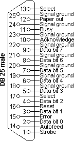
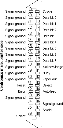
Parallel cablesStandard parallel cables are easy to obtain, but the link cable and test connectors which are shown here can often be better soldered by yourself.Parallel connector pinoutThe parallel port socket on your computer uses 25 pins. On most peripherals like printers, the 36 pins Centronics version is used. Both connector pinouts are shown here. The centronics socket is named after the company that introduced the first dot matrix printer in 1970, but after IBM and Epson took over the dot matrix printer market (later followed by Hewlett Packard in the laser and deskjet printer segment) most people only associate the word centronics with the port interface itself, not with a manufacturer.
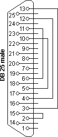
Parallel printer cableMost printers are connected to a computer using a cable with a 25 pins DB male connector at one side and a 36 pins centronics connector on the other. The normal way to make such a cable is shown here.
Interlink and Windows 95/98/ME DCC parallel cableThe following parellel cable can be used with file transfer and network programs like LapLink and InterLink. The cable uses the parallel port which makes it possible to achieve higher throughput than with a serial connection at the same low costs. The cable is amongst others compatible with the following software.
Because the parallel port on a computer was mainly designed to connect printers with one-way communication, a trick is used to achieve full two way data transfer between both sides. Five error and status message inputs are redefined as data inputs. Instead of reading full bytes, the communication software reads these five bits and combines multiple groups of data back to bytes. The sender and receiver have to use the same protocol to convert bytes to groups of 5 bits and vice versa.
Interlink and Windows 95/98/ME DCC parallel
cable 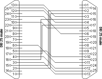
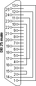
Parallel port test plugsBoth Norton Diagnostics and CheckIt have the ability to check the functionality of a parallel port. To do this, both software packages need a special plug on the port. Unfortunately, the pin layout of both connectors is not the same. The scheme of both sockets is given here.
| ||||||||||||||||||||||||||||||||||||||||||||||||||||||||||||||||||||||||||||||||||||||||||||||||||||||||||||||||||||||||||||||||||||||||||||||||||||||||||||||||||||||||||||||||||||||||||