|
High Definition Multimedia InterfaceIntroduction on the HDMI interfaceSince their introduction, computers have slowely changed from academic computing devices to general purpose household appliances. Where in the beginning mainly input and output devices like printers and modems were used, nowadays monitors, speakers and other audio and video equipment are often connected to computers. Most connections with these new devices were analog at first with either sending audio or video signals in an anlog fashion over a cable, buth with increased demands for output quality, and ever increasing speeds of the attached devices, analog was not the way to go anymore. What USB had done in the peripheral world by being a standard to connect any type of peripheral to any type of computer, the designers of the HDMI or High Definition Multimedia Interface wanted to do the equivalent in the world of audio and video.Video has long been the cowboy area of interfacing. With composite interfaces in the television and VCR world and RGB based interfaces in computers, there has never been a single direction for the developers. But with integration of the digital and analog world like for example in game consoles, there was a huge demand of one type of interface that could be used on computers as well as on VCRs, settop boxes, game consoles etc. The DVI Digital Visual Interface was the first succesful attempt to try to digitize visual information between digital generating equipment like computers and displays. DVI tried to be backward compatible by providing both an analog VGA level signal in the cable, and a digital encoded version. One of the major drawbacks in using the DVI interface on game consoles, VCR or settopbox devices was the lack of integration with audio. The DVI interface became the interface of choice for applications like CAD workstations, financial workstations etc, but it just couldn't find its way in the entertainment industry. Recognizing the success of the DVI interface in business, the seven founders of the HDMI interface: Hitachi, Matsushita Electric Industrial, Philips, Silicon Image, Sony, Thomson, and Toshiba used the DVI signal interface as the base for transmitting the digital signals. This interface had already proven its usefulness and driver chips and receiver chips for the interface were already in mass production. The DVI interface provides one or two digital high-speed channels to transport the data, with each channel capable of transporting 165 megapixels per second which is sufficient for a 2.75 megapixel screen at 60Hz refresh rate. In practice this is enough for a 1920x1200 WUXGA computer screen, or for a 1080p HD television. HDMI versionsIn the first specification of the HDMI interface HDMI 1.0, these speeds were directly copied from the DVI interface. Newer versions of HDMI allow higher pixel rates with 340 megapixel/sec starting with HDMI 1.3. Just as with DVI, two channels may be combined in a dual channel configuration giving a total of 680 megapixel/sec.The main difference between the DVI and HDMI interface is the audio signal wich is also transferred over the line. This interface carries no less than eight seperate uncompressed audio channels for applications like home-theaters with a maximum sampling rate of 192 kHz per channel. Sample depth can be as large as 24 bit. Besides that it can transfer compressed audio streams with the Dolby-Digital or DTS standard and since the HDMI 1.3 version it is also possible to use Dolby TrueHD and DTS-HD Master Audio over the HDMI interface. Because of its high speed, loss-less data transfer, integration of audio and video in one single flexible cable and allowed cable lengths which can reach 15 meter, HDMI became quickly the interface of choice for many multimedia devices. The backward compatibility with DVI makes it also easy to use older computers with newer equipment, with the only drawback that the audio signal should be connected over a different cable. Just as with VGA and DVI, an I²C compatible DDC channel is present on the interface. This channel can be used for control purposes and query the available video modes on the display. Since version HDMI 1.4 of the standard, a half-duplex ethernet communication has been added to the interface. To accomplish this, the hot-plug detection input and the last spare pin on the connector have been used for the differential lines of this ethernet channel.
HDMI connector pinoutThe pin layout of the HDMI interface connector is shown in the figure below.
HDMI connector pinout 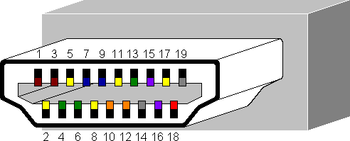
|
![]()