|
ДЕТЕКТОР НА ВОДА |
 |
|
ТЕХНИЧЕСКО ОПИСАНИЕ |
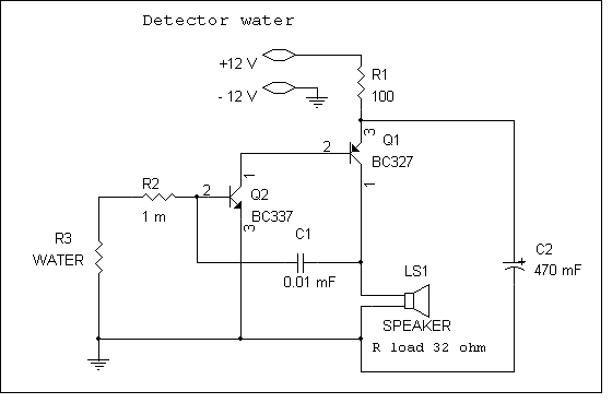
| Показана
е схема на прост индикатор
за наличието на вода .
Най-вече може да се използва за сигнализация при достигане до определено
ниво на водата в различни конструкции . Датчика
на устройството (съпротивлението на водата , показано като R3
на схемата) представлява обикновен електрически проводник . За повишаване
на надеждната
работа на устройството за електрод е необходимо да се използва метал,
устойчив на корозия , например посребрена пластина или от специална стомана . Особено
внимание да се обърне на устойчивото
свързване
на датчика със съединителния кабел на устройството , особено при големи
разстояния (няколко десетки метри ) . В този случай трябва да се използват
проводници с по-голямо сечение и е необходимо надеждно
да се заземят устройството и водната конструкция . При наличие на
недопустими смущения по свързващия проводник може да се конструира датчика
с два симетрични електрода и да не се използва заземяването на
конструкцията . |
Индикатор влажности
Очень простая схема, а пригодиться может: да везде. Можно
положить датчик в кошачий сортир, и вы всегда будете знать о состоянии
мочевого пузыря зверя. Правда есть опасность испугать животину, так что
будьте осторожны.
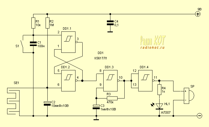
Схема индикатора:
Всего делов то, что одна микросхема. Когда
намокает датчик SE1, начинает пищать зуммер и загорается светодиод. Чтобы
выключить тревогу надо высушить датчик и нажать кнопку S1.
В схеме используется зуммер со встроенным
генератором. Конструкция датчика может быть любой, например можно
вытравить вот такой рисунок на куске фольгированного стеклотекстолита.
У микросхемы есть забугорный аналог - это CD4093.
Источник: www.radiokot.ru
|
|
Индикатор влажност

Котрол ниво вода

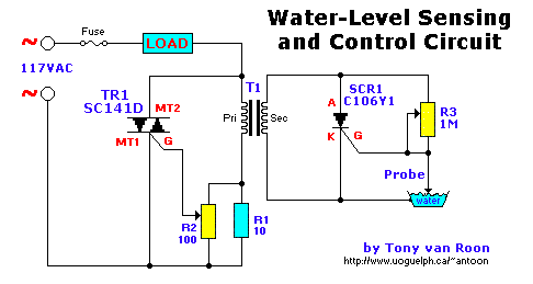
Parts List

  R1 = 10 ohm, 10 watt, wirewound
  R2 = 100 ohm, potentiometer, wirewound
  R3 = 1 Mega-ohm potentiometer
  T1 = Transformer, 12.6volt, 1.2amp (min)
SCR1 = Silicon Controlled Rectifier, C106Y1, NTE5452, or equivalent
 TR1 = TRIAC, SC141D, NTE5608, etc., rated 6-10 amp, 200-400 volt. TO-220.

Fuse = Slow-blow, 2 amp.
This is a simple but reliable circuit for your sump-pump, aquarium, boat, or whatever, but water only. Please be
careful when working with 115Volt line voltage! Take every precaution to avoid electrical shock. Unplug the
power before making changes or touching resistor R1. Murphy's Law applies to all of us!

This circuit is NOT suitable for use with
flammable liquids!!!
A Couple Notes:
Triac TR1 energizes a load which might control a valve, indicator light, audible alarm, relay, etc. The SC141D can be
substituted with NTE5608, NTE5635, or Radio Shack 276-1001 model.
When the water-level is "low", the probe is out of the water and SCR1 is triggered "on". It conducts and imposes a
heavy load on Transformer T1's secondary winding. That load is reflected back into the primary, gating TR1 on which
energizes the load. The C106Y1 can be substituted with a NTE5452 or Radio Shack (or Tandy) 276-1352
T1 is 12.6V not 12V.
Applications of the circuit are limited only by one's imagination.
The load may vary from a water valve, a relay controlling a pump, etc. Lots of possibilities. Value of the (slow-blow)
fuse may vary depending on your load. Select your probe carefully, keeping in mind the hardness and/or pH level of
the water. In either case, on occasion it will be necessary to clean your probe from contaminants.
If your country's electrical supply is 220VAC change TR1 to a 400 - 600 volt type, potentiometer R2 to 220 - 500 ohms.
If you find that 500 ohms is too coarse go with 220 ohm.
Experiment with the value for wire-wound resistor R1. It can be anywhere from 5 to 47 ohms. Start with 15 ohms or
so and take it from there. Feel if it gets real hot (unplug the power first!). If so, increase the value.

Circuit Notes The circuit uses a 555 timer wired as an
astable oscillator and powered by the emitter current of the BC109C. Under dry
conditions, the transistor will have no bias current and be fully off. As the
probes get wet, a small current flows between base and emitter and the
transistor switches on. A larger current flows in the collector circuit enabling
the 555 osillator to sound.
An On/Off switch is provided and remember to
use a non-reactive metal for the probe contacts. Gold or silver plated contacts
from an old relay may be used, however a cheap alternative is to wire alternate
copper strips from a piece of veroboard. These will eventually oxidize over but
as very little current is flowing in the base circuit, the higher impedance
caused by oxidization is not important. No base resistor is necessary as the
transistor is in emitter follower, current limit being the impedance at the
emitter (the oscillator circuit).
Description A circuit that offers visual indication of
fluid level in a vessel, with a switchable audible alarm. Example uses would be
to monitor the level of water in a bath or cold storage tank.
The Conductance of Fluids Conductance is the reciprocal of
resistance. The conductance of fluids vary with temperature, volume and
separation distance ofthe measurement probes. Tap water has a conductance of
about 50 uS / cm measured at 25°C. This is 20k/cm at 25°C.
Circuit Notes This circuit will trigger with any fluid with
a resistance under 900K between the maximum separation distance of the probes.
Let me explain further. The circuit uses a 4050B CMOS hex buffer working on a 5
volt supply. All gates are biased off by the 10M resistors connected between
ground and buffer input. The "common" probe the topmost probe above probe 1 in
the diagram above is onnected to the positive 5 volt supply. If probe 1 is
spaced 1 cm away from the common probe and tap water at 25 C is detected between
the probes (a resistance of 20k) then the top gate is activated and the LED 1
will light. Similarly if probe 2 at 2 cm distance from the common probe detects
water, LED 2 will light and so on. Switch 1 is used to select which output from
the hex buffer will trigger the audible oscillator made from the gates of a CMOS
4011B IC.
Placement of Probes As 7 wires are needed for the probe I
reccommend the use of 8 way computer ribbon cable. The first two wires may be
doubled and act as the common probe wire. Each subsequent wire may be cut to
required length, if required a couple of millimetres of insulation may be
stripped back, though the open "cut off" wire end should be sufficient to act as
the probe. The fluid and distance between probe 6 and the common probe wire must
be less than 900k. This is because any voltage below 0.5 Volt is detected by the
CMOS IC as logic 0. A quick potential check using a 900k resistance and the
divider formed with the 10M resistor at the input proves this point:
5 x (0.9 / (0.9+10) = 0.41 Volt
As this
voltage is below 0.5 volt it is interpreted as a logic 0 and the LED will light.
If measuring tap water at 25 C then the distance between top probe and common
may be up to 45 cm apart. For other temperatures and fluids, it is advisable to
use an ohmmeter first. When placing the probes the common probe must be the
lowest placed probe, as the water level rises, it will first pass probe 1, then
2 and finally probe 6.
Notes (English follows)
:
Ovaj sklop je projektiran da ukljuci relej kada se na knotaktima
pojavi voda.Tranzistor T1 moze biti zamijenjen s 2N2222A.Tranzistor T2 mora biti
BC108. Na kolektor tranistora T1 osim releja mogu biti spojeni signal injektor,
LE dioda, zarulja i ostali signalizacijski elementi.
In his circuit Marin
has used two transistors wired as a high gain compound pair. Transistor T1 may
be a 2N2222A and T2 a BC108. The current gain will be the product of each
transistors beta, which will be a minimum of 140 x 110 or 15400. The power
supply used can be any voltage from 4.5 to 15 volts, a typical 5 volt relay may
require 60 mA to operate, in which case any fluid which passes a minimum current
of 4 uA will activate the relay. This is easily achieved with tap or rain
water.

|


