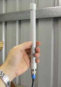
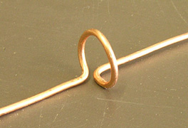
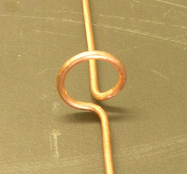
Design Details This collinear simply consists of a length of copper wire with some loops located at specific locations. The dimensions of the sections of the antenna are important, and are shown in the diagram below.  dimensions of the collinear The length of the bottom section is 1/2 wavelength (the left section in the diagram above), the centre section is 3/4 wavelength, and whip section on the top is slightly less than 3/4 wavelength, apparently to reduce the capacitance effect. The 802.11b standard uses 2.412GHz to 2.484GHz frequency range, so at the centre of that frequency range, 1/2 wavelength is 61mm, and 3/4 wavelength is 91.5mm. These dimensions appear to be consistent with similar commercial antennas. Construction Start construction of the antenna from the bottom end, and solder one length of the copper wire into the N connector. Measure 1/2 wavelength from the top of the N connector, and create the first loop.
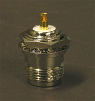
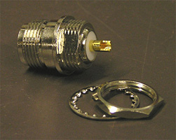
Note that the loops are offset from the wire which makes the vertical section of the antenna. Then measure an additional 3/4 wavelength, and create the second loop. Trim the whip section on the top so it's the correct length. If you are intending to use a length of 20mm conduit to house your antenna, be sure to keep the diameter of the coils to approximately 15mm or less, to ensure they will fit inside the conduit (20mm light-duty electrical conduit has an internal diameter of 16mm). 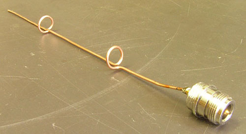 completed collinear However, a length of copper wire isn't particularly robust. One of the easier ways to address this shortcoming is to enclose the antenna inside a radome. Note that you need to use something that's transparent to 2.4GHz, else it will adversely affect the performance and operation of your antenna. I used a 250mm length of 20mm light-duty electrical conduit, with some end caps to suit. The 20mm light-duty conduit has an internal diameter of 16mm, and the loops bent in the copper were a snug fit inside the conduit. If you need something a little more roomy, then 25mm light-duty conduit can be used. Two small bends are required in the wire near the base of the antenna, to ensure that the loops are centrally located above the N connector, thus allowing the entire antenna to be inserted into the conduit. Testing indicates these bends to not have any noticable impact on the performance of the antenna. 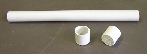 20mm conduit and end caps To mount the antenna, a suitably sized hole was drilled in one of the end caps, and after discarding the N connector's nut and washer, the N connector was screwed into the end cap from the outside. 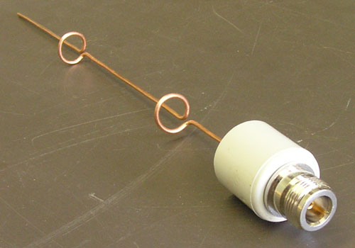 N-type connector screwed into an end cap The antenna can now be inserted into the conduit, and the other end cap can be installed. 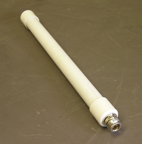 enclosed collinear If the antenna is to be used outdoors, the end caps should be glued on with appropriate conduit glue, to ensure a weather-proof seal. Note that the antenna should be tested before gluing the end caps in place. Mounting The collinear antenna is designed to be mounted vertically. The conduit radome provides a robust and sturdy enclosure for the antenna, and if required, it can be mounted outside in the weather. If mounting it outside, be sure to wrap the N-connector appropriately in self-amalgamating tape to prevent any moisture ingress. Plastic clamps made specifically for conduit can be used to attach the antenna to a vertical surface. As these clamps are plastic, they will not interfere with the operation of the antenna, while all-metal mounts placed in the radiation pattern could affect the operation of the antenna. 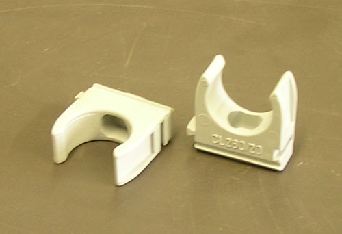 20mm conduit clamps After attaching the clamps to the surface where the antenna is to be mounted, the antenna can easily be clipped into the clamps, and can also be easily removed. 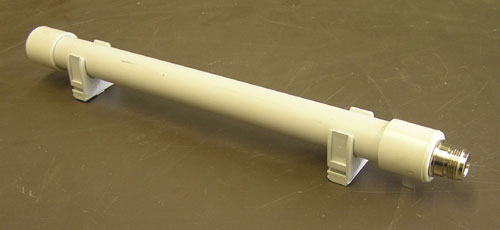 sample mounting using clamps An alternative method of mounting the antenna is with a short length of right-angle galvanised steel. A suitable hole needs to be drilled in one side, and the antenna can be attached to the galvanised steel by removing the N-connector and attached copper antenna, and passing it through the hole in the galvanised steel. The antenna will be firmly attached between the N-connector and the end cap. 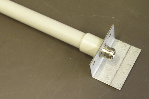 using a metal bracket If you just want to use the antenna for casual stumbling or wardriving, there is no need to mount it, and it can just be used as a handheld antenna. 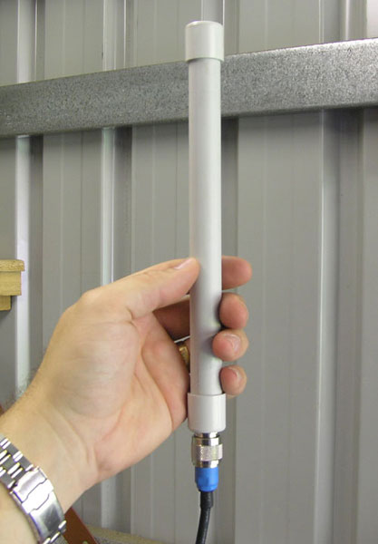 demonstrating just how small it is Testing When building my first collinear using this design, I made the loops in a similar way to those seen on many commercial antennas which have multi-loop coils, with the wire above and below the coil being centrally located with regards to the loop. 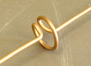 first attempt at the loops However, after doing some further research, I realised this was incorrect, and made another collinear using the loops as per the approach described above. Some quick comparison testing indicates the collinear with the offset loops performs much better than the collinear with the centered loops. Need More Gain? More gain can be achieved by adding additional segments to the middle of the collinear, as shown in the diagram below.  dimensions of a longer variation of the collinear Some quick comparison testing indicates this longer collinear has approximately 2dBi more gain than the 6dBi version, with a gain of about 8dBi. Note that lengthening the collinear antenna in this way will reduce the vertical beamwidth of the radiation pattern. | |||||||||||
