Parts List:
BR1 = Bridge Rectifier                 *C1 = 1000uF/63V, electrolytic (see text)
IC1 = LM317, adjustable regulator       C3 = 0.1uF (100nF), ceramic
  V = Meter, 30V, Ri = 85 ohm           C4 = 1uF/40V, electrolytic
TR1 = Transformer 24VAC, 3A           Plug = 3-wire plug & cord
 R1 = 1K8, 5%                           S1 = On-Off toggle switch
 R2 = 220 ohm, 5%                       D1 = 1N4001
 R3 = 27K, 5%                         Fuse = 115V, 500mA, slow-blow
 P1 = 5K, potentiometer               FuseHolder, enclosure, knob for P1
 P2 = 10K, Bourns trim-pot            Red & Black Banana Jacks, coolrib for IC1.

KIT Available [CLICK HERE]
Variable Power Supply, Regulated
 Description:
This is a simple, but low-ripple power supply, and an excellent project if you're starting out in electronics. It will
suit your needs for most of your bench testing and prototype applications. The output is adjustable from 1.2 volts to
about 30 volts. Maximum current is about 1.5 amps which is also sufficient for most of your tinkering. It is
relatively easy to build and can be pretty cheap if you have some or all the required parts.
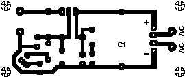
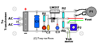
A printed circuit board is included farther down the page for those who like to make their own, but the whole thing can
easily be build on perforated or vero board. Or buy one of Radio Shack/Tandy's experimenters boards (#276-150). The
meter and the transformer are the money suckers, but if you can scrounge them up from somewhere it will reduce the
cost significantly.
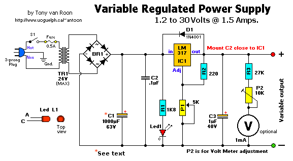
BR1 is a full-wave bridge rectifier. The two '~' denotes 'AC' and are connected to the 24vac output coming from the
transformer. The PCB is designed for the MDA201 which is a 100V/2A type, the MDA201A is a 4A type. You can use anything
you have in your junk-box with a minimum of 2A, but that is cutting it close. A 4 amp model would be a lot safer.
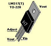
IC1 is a 3-pin, TO-220 model, but the TO-3 model can also be used. Be sure to put a cooling rib on IC1, at it's max
1.5 A current it quickly becomes very hot...
Most of the parts can be obtained from your local Radio Shack or Tandy store. The physical size of the power supply
case depends largely on the size of the meter & transformer. But almost anything will do, even wood. Go wild.
Have a beer with it.
Variable Power Supply, Regulated
Circuit Description:
The 117VAC (or 220VAC) coming from the power-cord is fed to the transformer TR1 via the on-off switch and the 500mA fuse.
The 24VAC output (approximately) from the transformer is presented to the bridge rectifier BR1, and here rectified from
AC (Alternating Current) to DC (Direct Current). If you don't want to spend the money for a Bridge Rectifier, you can
easily use four heavy duty, general purpose power diodes.
Whatever type transformer you get or purchase, make sure it does not exceed 24VAC. The LM317's max input voltage is
36V. 24VAC x 1.44pp = 34.56Vdc so right at the maximum edge. Better to obtain a transformer with a little less
voltage and be safe. A 18VAC transformer will still give you about 26VDC and more then anyone hobbyist ever need.
The amperage of the transformer should be 3A or so. That way it does not get hot.
The pulsating DC output from BR1 is filtered via the 2200uF capacitor (to make it more manageable for the regulator)
and fed to 'IN'-put of the adjustable LM317 regulator (IC1). The output of this regulator is your adjustable voltage
of 1.2 to 30 volts varied via the 'Adj' pin and the 5K potmeter P1. The large value of C1 makes for a good, low ripple
output voltage.
Why exactly 1.2V and not 0-volt? Very basic, the job of the regulator is two-fold; first, it compares the output
voltage to an internal reference (1.2V) and controls the output voltage so that it remains constant, and second, it
provides a method for adjusting the output voltage to the level you want by using a potentiometer. Internally the
regulator uses a zener diode to provide a fixed reference voltage of 1.2 volt across the external resistor R2. (This
resistor is usually around 240 ohms, but 220 ohms will work fine without any problems). Because of this, the voltage
at the output can not decrease below 1.2 volts, but as the potentiometer (P1) increases in resistance the voltage
across it, due to the current from the regulator plus current from R2, its voltage increases. This increases the
output voltage.
The circuit was modified to make C1 1000uF. It seemed more than enough for most applications. If you need more ripple
filtering then you can replace C1's value for a larger one, like 2200uF. Or use two 1000uF in parallel. If you do,
make *sure* the working voltage on each cap is the same, like 63V. Unlike values will make problems...
Trimpot P2 is to set the meter equal to the output voltage.
D1 is a general purpose 1N4001 diode, used as a feedback blocker. It steers any current that might be coming from the
device under power around the regulator to prevent the regulator from being damaged. Such reverse currents (spikes)
usually occur when devices are powered down. Basically, you can use any diode in the 1N400x series, it is not critical.
The 'ON' Led will be lit via the 1.8K (1800 ohm) resistor R1. The current through the led will be between 12 - 20mA @
2V depending on the type and color Led you are using. You may need to modify the value of R1 depending on your type LED.
C2 is a 0.1uF (100nF) decoupler capacitor to filter out the transient noise which can be induced into the supply
by stray magnetic fields. Under normal conditions this capacitor is only required if the regulator is far away from
the filter cap, but I added it anyway. C3 improves transient response. This means that while the regulator may
perform perfectly at DC and at low frequencies, (regulating the voltage regardless of the load current), at higher
frequencies it may be less effective. Adding this 1 uF capacitor should improve the response at those frequencies.
R3 and the trimmer pot (P2) allows you to 'zero' your meter to a set voltage. The meter is a 30Volt type with an
internal resistance of 85 ohms. I you have or obtained a meter with a different Ri (internal resistance) you will
have to adjust R3 to keep the current of meter to 1mA. Just another note in regards this meter, use the reading as a
guideline. The reading may or may not be off by about 0.75volts at full scale, meaning if your meter indicates 30
volts it may be in reality almost 30.75 volts or 29.25 volts. If you need a more precise voltage, then use your
multimeter.
Construction:
Because of the few components you can purchase a small case or use whatever you have available.
I used a power cord from a computer and cut the computer end off. All computer power cords are three-prong. The
ground wire, which is connected to the middle pin of the power plug is connected to the chassis. The color of the
ground-wire is either green or green/yellow. It is there for your protection if the 110vac accidentally comes in
contact with the supply housing (case). BE CAREFUL always to disconnect the powerplug when you working inside the
chassis. If you choose to use an in-line, or clip-type fuseholder be sure to isolate it with heat shrink or something
to minimize accidental touching.
I use perf-board (or Vero board) as a circuit board. This stuff is widely available and comes relatively cheap. It
is either made of some sort of fiber material or Phenolic or Bakelite material. They all work great. Some Phenolic
boards come with copper tracks already on them which will make soldering the project together easier.
I mounted the LM317T regulator on a heatsink. If you use a metal/aluminum case you can mount it right to the metal
case, insulated with the mica insulator and the nylon washer around the mounting screw. Note that the metal tab of
the LM317 is connected internally to the 'Output' pin. So it has to be insulated when mounting directly to the case.
Use heat sink compound (comes in transparent, white, or pink color) on the metal tab and mica insulator to maximize proper
heat transfer between LM317 and case/ or heatsink. Also, use non metalic stand-offs to mount the circuit board
in a metal or aluminum case.
Drill the holes for the banana jacks, on/off switch, and LED and make the cut-out for the meter. It is best to mount
everything in such a way that you are able to trouble-shoot your circuit board with ease if needed. One more note
about the on-off switch S1, this switch has 110VAC power to it. After soldering, insulate the bare spots with a bit
of silicon gel. Works great and prevents electrical shock through accidental touching.
Variable Power Supply, Regulated
If all is well, and you are finished assembling and soldering everything, check all connections. Check capacitors C1
& C3 for proper polarity (especially for C1, polarity reversal may cause explosion). Hookup a multi-meter to the
power supply output jacks.
Set the multi-meter for DC volts. Switch on S1 (led will light, no smoke or sparks?) and watch the meter movement.
Adjust potentiometer P1 until it reads on your multi-meter 15Volts. Adjust trimpot P2 until the panel meter (if so
installed) also reads 15volts. The panel voltmeter is optional.
When done, note any discrepancies between your multi-meter and the power supply meter at full scale (max output).
Maybe there is none, maybe there is little, maybe there is a lot because of your choice of transformer but you will be
aware of it. Just make sure your multimeter reading and panel meter read as close as possible.
Good luck and have fun building!


Substitutes:
IC1: LM317T (TO-220), NTE956, ECG956
IC1: LM317K (TO-3), NTE970, ECG970
BR1: KBPC801, NTE5312, ECG5312
D1: 1N400x, NTE116, ECG116
Final Notes:
You can add two silicon diodes (1N400x in series) to the output of the LM317 to drop the final 1.2V, giving the full 0-30V
range. I built a similar supply using the LM317, to supply a wafer coating spinner motor. The 1.2V kept the motor
spinning at over 100rpm, which was unacceptable to the researcher, who needed to ramp the motor speed from 0-8krpm.
The LED remains lit after switching off the power and slowly bleeds off via electrolytic capacitor C1, this is normal.
Variable Power Supply, Regulated, LM317
Back to ..


 Description:
