Electronics - USB Powered AA NiMH and NiCd Battery Charger - Stefan Vorkoetter| USB Powered AA NiMH and NiCd Battery Charger I'm always complaining about all the chargers and wall warts I need to carrywith me when going on a trip. This project, which can charge a pair of AANickel Metal Hydride (NiMH) or Nickel Cadmium (NiCd) cells using a laptop's USBport for power, arose to address part of that problem. Any USB port can supply 5V at up to 500mA. The USB standard specifies that adevice may not use more than 100mA until it has negotiated the right to use500mA, but apparently no USB ports enforce that requirement. This makes the USBport a convenient source of power for devices such as this charger. There are commercially available USB AA charging solutions available, but theyeach have some drawbacks: The USBCell is a 1300mAhAA NiMH cell with a removable top that allows it to be plugged directly intoa USB port. No separate charger is needed. Unfortunately, the cell capacityis very low (most NiMH AA cells are 2500mAh these days), and each cellrequires its own port. There is a two cell USB powered AA chargeravailable, sold under a variety of names, but it charges at a very low 100mArate. The distributor calls it an "overnight charger", but at 100mA, a2500mA cell would take about 40 hours to charge (40 instead of 25 due to theinefficiencies of charging at low currents). I found a2/4 cell chargerthat can be powered by a USB port, auto adapter, or wall wart, but it is aslarge as the wall charger I'm trying to replace. Different ones can be foundhere and,but these take 10 to 12 hours to charge 2500mAh cells.
[December 2007 Update: Sanyo has introduced aUSB powered charger for their Eneloop batteries.This charger has none of the drawbacks listed above, and will charge a pair of2000mAh cells in about 5 hours, or a single cell in half that time. ] The charger in this project is designed to charge two AA NiMH or NiCd cellsof any capacity (as long as they are the same) at about 470mA. It willcharge 700mAh NiCds in about 1.5 hours, 1500mAh NiMHs in about 3.5 hours,and 2500mAh NiMHs in about 5.5 hours. The charger incorporates an automaticcharge cut-off circuit based on cell temperature, and the cells can be leftin the charger indefinitely after cut-off. SpecificationsThis charger has the following specifications:- Size: 3.8"L x 1.2"W x 0.7"H (9.7cm x 3.0cm x 1.5cm).
- Cells: Two AA, NiMH or NiCd
- Charging Current: 470mA
- Charge Termination Method: Battery Temperature (33°C)
- Trickle Current: 10mA
- Power Source: Desktop, Laptop, or Hub USB port
- Operating Conditions: 15°C to 25°C (59°F to 77°F)
The CircuitThe heart of this charger is Z1a, one half of an LM393 dual voltage comparator.The output (pin 1) can be in one of two states, floating or low. Whilecharging, the output is pulled low by an internal transistor, drawing about5.2mA of current through Q1 and R5. Q1 has a beta of about 90, so about 470mAwill flow through into the two AA cells being charged. This will fully charge apair of 2500mAh cells in just over 5 hours.  | | USB powered AA charger schematic. |
During charging, R1, R2, and R4 form a three-way voltage divider which yieldsabout 1.26V at the non-inverting input of Z1a (pin 3, Vref). TR1 is a thermistor that is in direct contact with the cells being charged.It has a resistance of 10kΩ at 25°C (77°F), which variesinversely with temperature by about 3.7% for every 1C° (1.8F°). R3 andTR1 form a voltage divider whose value is applied to the inverting input(pin 2, Vtmp). At a temperature of 20°C (68°F), TR1 is about12kΩ, which makes Vtmp about 1.76V. Once the cells are fully charged, the charge current will literally go towaste, in the form of heat. As the cell temperature rises, TR1's resistancedrops. At 33°C (91°F), the resistance will be about 7.4kΩ, whichmakes Vtmp about 1.26V, which equals the Vref voltage. | |  | | Battery voltage versus time. The cells are full when the voltage peaks, and the charger shuts off shortly thereafter. |
As the temperature rises above 33°C, Vtmp will become less thanVref, and the open-collector output of Z1a will float high.Therefore, the current flowing through R5 is greatly reduced, as it is nowlimited by R1, R2, and R4. As a result, the current flowing through Q1 and thecells is reduced to a 10mA trickle charge rate.Also, because R4 is now connected to +5V through R5 and Q1 instead of beingheld at 0.26V by Z1a, the Vref voltage changes to about 2.37V. Thisguarantees that as the cell temperature drops, the charger won't turn back on.In order for Vtmp to reach 2.37V, TR1 would have to reach about20kΩ, corresponding to a temperature of about 6°C (43°F), whichshould never happen in a room temperature environment. Z1b is the other comparator on the LM393 chip, and a close look at theschematic reveals that it's performing the same comparison as Z1a. Instead ofdriving the charging transistor however, it drives an LED that indicates thatcharging is in progress. R6 limits current to the LED to about 10mA. Byrunning the LED from its own comparator (which is on the chip whether we useit or not), the LED current has no effect on Vref. Finally, C1 is there to ensure that charging starts when a pair of cells isinserted. With no cells in place and the charger off, C1 has about 1.9V acrossit (5V - 0.7V - Vref). As soon as the second of two cells is inserted, thepositive side of C1 is suddenly forced down to the battery voltage (about2.4V). This immediately forces the negative side 1.9V lower than this, to about0.5V. Since this is connected to Vref, Z1a's output goes low,causing charging to start. After a few milliseconds, C1 adjusts to the newvoltage difference imposed by R1, R2, and R4 on one side and the cells on theother, and no longer affects the circuit. ConstructionThe circuit is best built on a printed circuit board. Refer to my articleon the subject, MakingExcellent Printed Circuit Boards. Here is the printed circuitlayout:  | | Copper side. Actual size is 3.8" x 1.2" (9.7cm x 3.0cm). Click to enlarge. |
Begin by installing all the resistors and the capacitor. The resistors shouldbe installed lying flat. Install LED1, being sure to orient it so that thenegative terminal is the one connected to pin 7 of Z1b.  | | Component placement diagram. Click to enlarge. |
Install Z1 next, ensuring that pin 1 (indicated by a small dot or identationon one corner of the IC) is oriented as shown in the placement diagram. If youwish, use a socket for Z1. Transistor Q1 is mounted on a small heatsink. First bend the leads back 90°just where they start to narrow. Don't bend them too sharply or they mightbreak. Insert Q1 into its lead holes, and slide the heatsink underneath. Holdeverything in place with a clamp while soldering the leads. With the clampstill in place, drill the hole for the heatsink bolt. 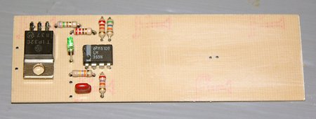 | | Charger with all electronic components installed. Note that there is space under Q1 for the heatsink. The board area where the battery holder will go has been scuffed up to aid adhesion. |
Installing the battery holder is the next step. I used a 2-cell holder made bycutting the two outer cell positions off of a side-by-side 4-cell holder. Youcan of course just buy a 2-cell holder, but none was available when I wentto the parts store. My approach has the additional advantage that the cellsare easier to insert and remove, because the sides of the holder don't curveinwards over the cells. Before installing the holder, remove a ¼" long section of the centredivider to make room for the thermistor. Also solder some leads to the cellholder terminals. Glue the holder in place on the circuit board, flush withthe sides and ends of the board. When the glue has dried, drill through theTR1 holes in the board to make matching holes in the battery holder. If youdid everything carefully, these two holes should be right on the centre line,where you removed the section of divider. Insert the thermistor through the holes, and then put a pair of AA cells inthe holder. From the copper side, push up on the thermistor so it is in firmcontact with the cells, and then solder it in place. Then remove the cells,and connect the battery holder leads to the holes marked B+ and B- on theplacement diagram. 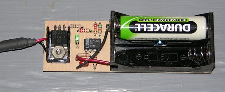 | | The completed charger with one cell in place. The 2-cell holder was made by cutting the outer positions off of a 4-cell holder. Notice how the thermistor is installed so as to make physical contact with the cells being charged. A small heatsink keeps Q1 cool. |
The last step is to connect a USB power cable. Either buy a cable, or cut oneoff of a discarded USB device such as a broken mouse. Cut the cable to thedesired length, and strip about 1" of the outer covering off the end. Roll backthe shielding, and find the +5V and GND wires. These will generally be redand black respectively. Strip and tin the ends of them, and solder them tothe USB+5V and USBGND terminals of the charger. TestingBefore connecting the charger to a power source, inspect your work carefully.Be sure all the components are oriented correctly (specifically Q1, LED1,Z1, and the battery holder). 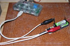 | | | For initial tests, I used a USB hub for power. A pair of #11 hobby knife blades between the cells and the contacts let me hook up a voltage monitor. |
For initial tests, I suggest you use a powered USB hub. By using a hub, youensure that the charger is not drawing power from your computer, since a defectin the charger could damage the power source. Note however that most poweredhubs won't output any power unless the hub is connected to a computer.Alternatively, you could use a regulated 5V power supply, temporarily connectedto the +5V and GND traces on the circuit board.With power applied, check that the LED is off. If it is on, use a 330Ωresistor to short out TR1 for an instant (this makes the circuit think thecells have gotten extremely hot). If the LED doesn't extinguish, there'ssomething wrong. With the LED off, measure the voltage between GND and Vref (pin 3of Z1). This should be approximately 2.37V. It can be a bit more or lessdepending on the exact supply voltage and the variation in resistor values.Also check the voltage at Vtmp (pin 2). At room temperature, thisshould be in the range of 1.60V to 1.85V, depending on the temperature. Now insert a pair of matching AA NiMH cells, preferrably ones that arepartially or fully discharged. As soon as you insert the second cell, the LEDshould light up. Measure the Vref voltage again; it should now beabout 1.26V. Vtmp may also have changed a little bit, due to thesupply voltage drop caused by the load placed on the power supply. The charger is now charging and the voltage at the battery terminals should beincreasing. After a while, the rate of increase should slow down. As thecells reach about 75% charge, the rate of increase will speed up again. Finally,when the cells reach 100% charge, the voltage will start decreasing, and thecells will start to get warm. 15 to 20 minutes later, the charger should turnoff. If the cells get uncomfortably warm and the charger has not shut off,there's something wrong. It's also worth measuring the charge current. The easiest way to do this is toinsert two thin conductive strips, such as brass shim, separated by aninsulator, between one cell and a battery holder contact. Then connect anammeter to the two strips, so that the charging current flows through themeter. The meter should read somewhere between 450 and 490mA. If it's anyhigher, you will be exceeding the USB current supply specification, since thecharger itself uses an additional 10mA (primarily for the LED). If the measured current, I, is too high or too low, replace R5 witha different value resistor according to the following formula: R5 = 1.6 x I Use the nearest standard value. For example, if you measure a current of 510mA,replace R5 with an 820Ω resistor. If the measured current was 420mA, usea 680Ω resistor. EnclosureAt the time I wrote this, I had not yet constructed an enclosure for thiscircuit, but plan to do so in the near future, since the bare board is notrobust enough to throw into the laptop bag when going on a trip. The enclosurewill be made from 1/16" plastic or aircraft plywood for the sides and bottom,with a translucent plastic panel over the circuitry. The battery compartmentwill be left open. A strain relief will prevent the USB leads from breaking offwhere they attach to the board. For cooling, I plan to drill holes in the sidesand top in the heatsink area. Using the ChargerUsing the charger is easy. Just plug it into a USB port and insert the twocells you want to charge. When the LED extinguishes, charging is complete.Approximate charge times are as follows: | Cell Type | Charge Time |
|---|
| 700mAh NiCd | 1.5h | | 1100mAh NiCd | 2.5h | | 1600mAh NiMH | 3.5h | | 2000mAh NiMH | 4.5h | | 2500mAh NiMH | 5.5h |
It is important that the two cells being charged are of the same type andat the same level of discharge. If the cells are mismatched, one will becomefully charged before the other. When it reaches 33°C, the charger willshut off. If the second cell needs more than about 200mAh more than the firstcell, it will not have reached a full charge. | | 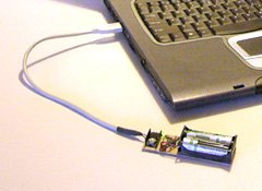 | | This charger, with a suitable enclosure, is ideal for use on trips, using a laptop to power the charger. The laptop should be plugged in to avoid running down its battery. |
In general, if two cells are used together in a single device (digital camera,GPS, etc.), then they will remain in sync, and can be charged together.When charging is completed, the charger will switch to a 10mA trickle charge.This is sufficient to overcome the cells' natural self-discharge rate, but lowenough that the cells can be left in the charger indefinitely. However,do not leave the cells in the charger unless the charger is pluggedinto a powered-up USB port. Otherwise, the cells will supply power to thecircuit and be drained in the process. When using this charger with any computer, make sure that the computer is notset to go into a power saving mode that turns off power to the USB ports. Ifthis happens, charging will stop, and the cells being charged will discharge. When using a laptop as a power source, it's best to plug in thelaptop's power supply, since the charger uses a significant amount of power,and will probably take longer to complete than the laptop battery will last. If powering this charger from a USB hub, be sure to use a powered hub. Anon-powered hub will not be able to deliver enough current to the charger,since it must share the 500mA coming from the computer with the ports in thehub (typically four). The extra cable length also tends to reduce the voltagereaching the charger. Charging AAA CellsIf the springs in the battery holder are long enough, the charger can alsobe used to charge a pair of AAA cells. However, it is then necessary to insertshims between the cells and the sides of the battery holder to ensure thatthe cells remain in contact with the thermistor. Only charge modern AAAcells, having a capacity of 700mAh or more. Parts ListSome parts can be obtained at Radio Shack, but larger electronic supplyhouses like DigiKey are more likely to stock all the parts needed. | Part | Description |
|---|
| R1 | 56kΩ ¼W, 5% resistor | | R2 | 27kΩ ¼W, 5% resistor | | R3 | 22kΩ ¼W, 5% resistor | | R4 | 47kΩ ¼W, 5% resistor | | R5 | 750Ω ¼W, 5% resistor | | R6 | 220Ω ¼W, resistor | | TR1 | 10kΩ @ 25°C thermistor, approx. 3.7%/C° NTC
Radio Shack #271-110 (discontinued†) | | C1 | 0.1µF 10V capacitor | | Q1 | TIP32C PNP transistor, TO-220 case | | Z1 | LM393 dual voltage comparator IC, DIP | | LED1 | Red, green, or yellow LED, 10mA | | Other | 2-cell AA battery holder
USB cable
Small heatsink |
†Note that the Radio Shack thermistor has been discontinued.Although I have not tried any of them, there are other similar thermistorsavailable, such as the Vishay #2381 640 54103 (Digi-Key #BC2298-ND). Thetemperature coefficient is slightly different (about 4.6%/C°), but over therange we're interested in, is close enough. Using this thermistor, the cut-offand turn-on temperatures would be about 32°C (89°F) and 10°C(50°F) respectively. Alternatively, you can use the resistor values below with the Vishay thermistorto raise the cut-off temperature back to 33°C, while lowering the turn-ontemperature to 3°C (37°F). | Part | Alternative Resistor Values to use with
Vishay #2381 640 54103 Thermistor |
|---|
| R1 | 82kΩ ¼W, 5% resistor | | R2 | 33kΩ ¼W, 5% resistor | | R3 | 27kΩ ¼W, 5% resistor | | R4 | 39kΩ ¼W, 5% resistor |
I have not tested this combination, but thevalues were computed using the same program that I used to compute the valuesthat were used with the Radio Shack thermistor. Do not mix and matchvalues from this table with those listed above. If you change any of the valuesto those in this table, change all of them. If anyone finds an alternate source for the Radio Shack thermistor, please letme know.
 |