Additional Notes
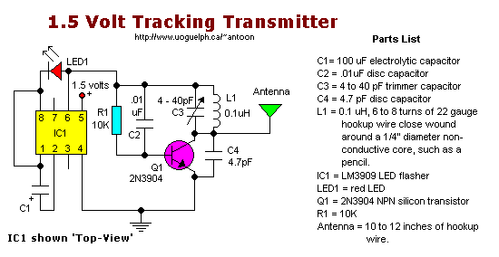
o For stability, use a NPO types for C2 & C4.
o Resistance tolerance for R1 should be 1 or 2%.
o Frequency range is the usual 87-109Mhz on the FM dial.
o The coil is made from 22 ga 'hookup' wire, like the solid Bell phone wire.
Leave the insulation on.
o The LED is the 'High Brightness' type for maximum illumination, although this type will draw more current.

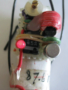
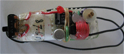
 The current draw for this tracker is 3.7mA, so the 1.5V button cell will last a while. My experimental version was
tuned to 87.6MHz and worked as expected on only 1.5 volts. The photo shows I just glued the whole thing on a 1.5V AA
battery. The led glows at the same oscillation as the beat-frequency
What the heck am I suppose to hear you ask? When your circuit is working you should see the LED flash quite fast.
Take your FM radio and search for the low-beat 'thumpe-thumpe-thumpe-etc' equal to the flash of the LED (probably
around the 100Mhz). Found it? If that position is interfering with a radio station you can fine-tune it with the
variable capacitor. If you like to have the tracker around the 88Mhz (or lower) you can do that by keeping the
windings from the home-made coil close together. Anyways, play with it and learn. It may take alot of patience to
find the signal but once you know where it is it becomes simple. It is a nice learning project.
To hear the sound of this beat: [Click Here]
The 12-inch antenna can be anything, it is not really that critical. I used a piece of 22 gauge flexible wire.
The range at 1.5V is limited to around 30 feet or less. At 3V it will be significantly different.
Back to ..


 The current draw for this tracker is 3.7mA, so the 1.5V button cell will last a while. My experimental version was
tuned to 87.6MHz and worked as expected on only 1.5 volts. The photo shows I just glued the whole thing on a 1.5V AA
battery. The led glows at the same oscillation as the beat-frequency