Testing a SCR
Silicon Control Rectifier
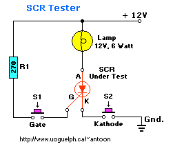
"This simple SCR tester can be made with only a couple components. It will provide a
visual 'go' or 'no-go' indication--it is simply a voltage source, a lamp, and a resistor through which gate current
is supplied."

This handy tester will provide a visual "on" or "off" switching and latching indication. When finished, you can test
all those posible 'duds' in your junkbox and dump some of those in the garbage. If the scr is latching and can hold
the latch it is most likely okay.
Look at the circuit diagram, it shows a 3-amp, 50-volt SCR (under test) and a test circuit. Points "Gate" and
"Kathode" are temporary connections, so that they can easily be opened. I used toggle switches for each, but use
whatever you feel comfortable with, a simple jumper wire would do the trick. I use this gadget in my shop and so
have it mounted in a small case. This circuit can even be bread-boarded for your purpose.
When "Kathode" is closed, the lamp doesn't light. When "Gate" is also closed, the lamp lights to its full
intensity. The lamp remains lit even if "Gate" is opened again. But when "Kathode" is opened, even momentarily,
the lamp does not close again when "Kathode" is closed. That illustrates the "ON" and "OFF" operation of the SCR.
I tested the following SCR types: C106D1 (400V/4A)         T106Y1 (30V/4A)
                                  C106F (50V/4A)           C106F1 (50V/4A)
                                  C106B (200V/4A)          CSM2B2 (100V/4A)
                                  T106D1 (400V/4A)         NTE5402 (100V/0.8A)
                                  TIC106M (600V/8A)        NTE5457 (400V/4A)
                                  TIC126M (600V/25A)       CR6AM-8 (400V/10A)
                                  MCR106-3 (100V/4A)       NTE5455 (200V/4A)

In all cases the tester was accurate in telling 'good' from the 'bad'.
TRIACS:
I decided to experiment the tester on TRACS since they operate on the same principle. The pin-out of a Triac is usually
MT1, MT2, and Gate. Hookup the probes as follows: The 'K' probe to 'MT1', the 'A' probe to 'MT2' and the 'G' probe to
'Gate'. I used a 9Volt and a 12Volt power-supply for bench testing purposes. Execute the tests the same way as a SCR.
The lamp should only be on when the K switch is on and G switches on momentarily. In any other condition the
lamp should remain off. If not, the Triac will almost certainly be defective. Keep the tests on any Triac as short
as possible.
I tested the following Triacs with good results:

     Q4006L4  (400V/8A)  - Tested Good (was new)
     Q6006LT  (600V/10A) - Tested Defective  (was defective)
     Q6010L5  (600V/10A) - Tested Good (was new)
     L4004F31 (400V/4A)  - Tested Defective  (was defective)
     MAC15A   (400V/15A) - Tested Good (was new)
     NTE5610  (800V/8A)  - Tested Good (was new)
Again, in all cases the tester was correct. I compared the results of the two defective Triacs with the results of a
very expensive commercial SCR/Triac tester. On the commercial tester you can set the actual VRM (volt) of a Triac and
check for leakage and what not but I found the end result the same; "is it good or bad" and is it "switching or not".
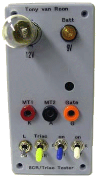
 I am planning to modify this circuit to include all
scr's and triac's, including sensitive gate units. See picture at the left. It is in the prototype stage, so far so good.
Back to ..

 I am planning to modify this circuit to include all
scr's and triac's, including sensitive gate units. See picture at the left. It is in the prototype stage, so far so good.