This sequence is also used by the USB connector but achieved rather more simply by using different length pins in the connector. The circuit shown here in Figure 1 performs the switching sequence electronically. The clock and data lines from the PC are connected via the N.C. contacts of relay RE2 through the bistable relay RE1 to connector K3. Pressing push-button S1 will activate relay RE2 thereby disconnecting the data and clock lines also while S1 is held down the semiconductor switch IC1B will be opened, allowing the voltage on C4 to charge up through R4. After approximately 0.2 s the voltage level on C4 will be high enough to switch on IC1A, this in turn will switch on T1 energizing one of the coils of the bistable relay RE1 and routing the clock, data and power to connector K2.
 |
 |
 |
 |
When S1 is released relay RE2 will switch the data and clock lines through to the PC via connector K1. It should be noted that the push-button must be pressed for about 0.5s otherwise the circuit will not operate correctly. Switching back over to connector K3 is achieved similarly by pressing S2. The current required to switch the relays is relatively large for the serial interface to cope with so the energy necessary is stored in two relatively large capacitors (C2 and C3) and these are charged through resistors R1 and R6 respectively. The disadvantage is that the circuit needs approximately 0.5 minute between switch-overs to ensure these capacitors have sufficient charge.
The current consumption of the entire circuit however is reduced to just a few milliamps. The PCB is designed to accept PS2 style connectors but if you are using an older PC that needs 9 pin sub D connectors then these will need to be connected to the PCB via flying leads. In this case the mouse driver software configures pin 9 as the clock, pin 1 as the data, pin 8 (CTS) as the voltage supply pin and pin 5 as earth.
Resistors:
R1 = 2kΩ2
R2 = 47kΩ
R3 = 10kΩ
R4 = 4kΩ7
R5 = 1kΩ
R6 = 1kΩ2
Capacitors:
C1 = 10µF 10V radial
C2 = 1000µF 10V radial
C3 = 2200µF 10V radial
C4 = 2µF2 10V radial
Semiconductors:
D1-D5 = 1N4148
T1 = BC547
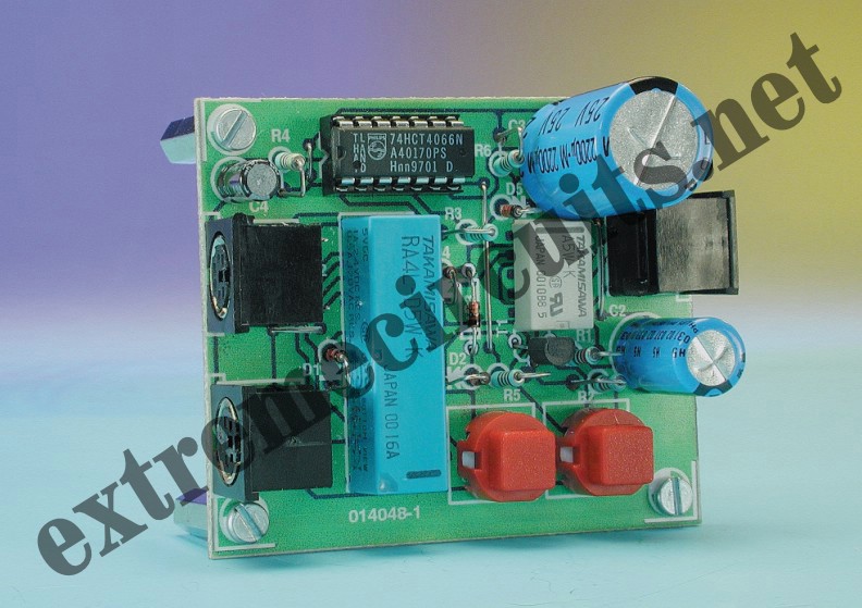
IC1 = 4066 or 74HCT4066
Miscellaneous:
RE1 = bistable relay 4 c/o contacts
RE2 = monostable relay 2 c/o contacts
K1,K2,K3 = 6-way Mini-DIN socket (pins at 240°, PCB mount
S1,S2 = push-button (ITTD6-R)
Back to ..