Potential Divider
A potential (or voltage) divider is made up of two resistors. The output voltage from a potential divider will be a proportion of the input voltage and is determined by the resistor values.
Operation:
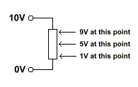
Consider a standard resistor connected across a voltage supply. If you were able to open it up and measure the voltage at any point along it you would find the voltage varied linearly along it (assuming the resistance was constant along it's length). For example if the resistor was connected between 10V and 0V the voltage half-way along it would be 5V. Similarly the voltage 10% from the 0V end would be 1V. The diagram below illustrates this:

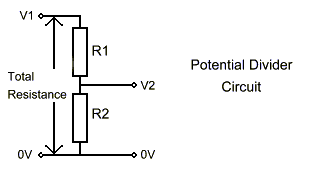
A potential divider works in the same way. Obviously a resistor is normally enclosed so you can't tap the voltage off at any point along it, so two resistors are used; the tap point being between these resistors. The diagram below shows a potential divider circuit with the standard component notation used:

V1 is the voltage in and V2 is the voltage out.
Equation:
The voltage out of the divider is determined by the resistor values using the equation:
V2 = (R2 / (R1 + R2)) * V1
By rearranging this and specifying the total resistance (R1 + R2) the resistor values can be found from the desired output voltage V2.
An interactive calculator for potential dividers can be found here.