Is it difficult or complicated to 'charge' a capacitor? Not at all. Put proper voltage on the legs of the capacitor and wait till current stops flowing. It goes very fast. Do NOT exceed the capacitor's working breakdown voltage or, in case of an electrolytic capacitor, it will explode.The break down voltage is the voltage that when exceeded will cause the dielectric (insulator) inside the capacitor to break down and conduct. If that happens the results can be catastrophic.And in case of a polarized capacitor, watch the orientation of the positive and negative poles. A healthy, good quality capacitor (disconnected) can hold a charge for a long time. From seconds to several hours and some for several days depending on its size. A capacitor, in combination with other components, can be used as a filter that blocks DC or AC, being it current, frequency, etc.
An interesting experiment for a classroom. Try to build another capacitor than the Leyden Jar yourself too. Cut two long strips of aluminum, say 1" wide by 48" long (25mm x 120mm).Cut two strips of paper 1.5" by 50" (38mm x 125mm). Make sure the paper is dry. The paper is a bit wider and longerthen the foil to prevent the strips of foil from touching each other when you roll them up and creating a short. Take two small metal paperclips and 'unbend' them. One paperclip/strip aluminum foil is designated 'Positive' and other one 'Negative'. Carefully roll up (all at once) the strips. One paperclip (or wire) goes with it. First layer is tin foil, second one is paper (the insulator), third layer is tin foil, and last layer is paper again. When you're almost at the end, don't forget the insert the other paperclip (or wire) with it. Make sure the paper is dry or it won't work. Don't forget the paperclips (or wire) and make sure the two strips don't touch each other. When you have the whole thing rolled up tightly as possible secure it with tape or an elastic band or whatever.
Measure with a multimeter that the foil strips are insulated from each other and not shorted.
Take a 9-volt battery and attach the negative (-) to one pole of the capacitor, and the other to your positive (+) pole.It only takes a fraction of a second to charge it up. You can check the charge by hooking up a voltmeter or if that isnot available short the 'capacitor' and you should see a little spark.
Capacitor Codes
I guess you really like to knowhow to read all those different codes. Not to worry, it is not as difficult as it appears to be. Except for the electrolytic and large types of capacitors, which usually have the value printed on them like 470uF 25V or something, most of the smaller caps have two or three numbers printed on them, some with one or two letters added to that value. Check out the little table below.
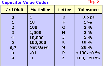
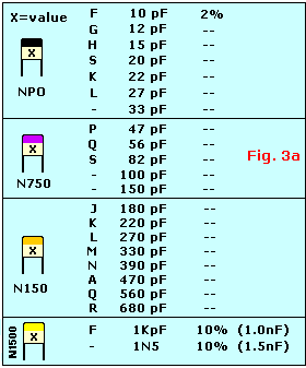
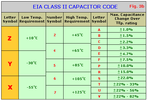
Have a look at Fig. 2 and Fig. 3. As you can see it all looks very simple. If a capacitor is marked like this 105, it just means 10+5zeros = 10 + 00000 = 1.000.000pF =1000 nF = 1 uF. And that's exactly the way you write it too. Value is in pF (PicoFarads). The letters added to the value is the tolerance and in some cases a second letter is the temperature coefficient mostly only used in military applications, so basically industrial stuff.
So, for example, it you have a ceramic capacitor with 474J printed on it it means: 47+4zeros = 470000 = 470.000pF, J=5% tolerance. (470.000pF = 470nF = 0.47uF) Pretty simple, huh? The only major thing to get used to is to recognize if the code is uF nF, or pF.
Other capacitors may just have 0.1 or 0.01 printed on them. If so, this means a value in uF. Thus 0.1 means just0.1 uF. If you want this value in nanoFarads just move the comma three places to the right which makes it 100nF.Easy huh?
"NPO" is standard for temperature stability and 'low-noise', it does *not* mean non-polarized even though you might think so because the abbreviation looks similar. Polarized ceramic capacitors do not exist. The abreviation "NPO" stands for "Negative-Positive-Zero" (what is read as an 'O' is actually zero), and means that the negative and positive temperature coefficients of the device are zero--that is the capacitance does not vary with temperature. ONLY the black top indicates NPO qualification and the values are in the range from 1.8pF to 120pF, unless manufactured with different values for Military and/or industrial purposes on special request. They feature 2% tolerance which comes down to about 0.25pF variation, and all are 100V types. You may sometimes find NPO-type caps marked witht he EIA (Electronic Industrial Association) code "COG". The EIA has an established set of specifications for capacitor temperature characteristics (EIC 384/class 1B). Thus, a capacitor labeled "Y5P" would exhibit a plus/minus tolerance of 10% variation in capacitance over a temperature range of -30°C. to +85°C. Or it may say N12 which translates to 120pF. Or 2P2 (2.2pF). I'm sure you get the idea...
But the average hobbyist uses only a couple types like the common electrolytic and general purpose ceramic capacitors and depending on the application, a more temperature stable type like metal-film or polypropylene.
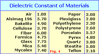
The larger the plate area and the smaller the area between the plates, the larger the capacitance. Which alsodepends on the type of insulating material between the plates which is the smallest with air. (You see this type of capacitor sometimes in high-voltage circuits and are called 'spark-caps'.) Replacing the air space with an insulator will increase the capacitance many times over. The capacitance ratio using an insulator material is called Dielectric Constant while the insulator material itself is called just Dielectric. Using the table in Fig. 4, if a Polystyrene dielectric is used instead of air, the capacitance will be increased 2.60 times.
Look below for a more detailed explanation for the most commonly used caps.
 Electrolytic - Made of electrolyte, basically conductive salt in solvent. Aluminum electrodes are used by using a thin oxidation membrane. Most common type, polarized capacitor. Applications: Ripple filters, timing circuits. Cheap, readily available, good for storage of charge (energy). Not very accurate, marginal electrical properties, leakage, drifting, not suitable for use in hf circuits, available in verysmall or very large values in uF. They WILL explode if the rated working voltage is exceeded or polarity is reversed, so be careful. When you use this type capacitor in one of your projects, the rule-of-thumb is to choose onewhich is twice the supply voltage. Example, if your supply power is 12 volt you would choose a 24volt (25V) type. This type has come a long way and characteristics have constantly improved over the years. It is and always will bean all-time favorite; unless something better comes along to replace it. But I don't think so for this decade; polarized capacitors are heavily used in almost every kind of equipment and consumer electronics.
 Tantalum - Made of Tantalum Pentoxide. They are electrolyticcapacitors but used with a material called tantalum for the electrodes. Superior to electrolytic capacitors,excellent temperature and frequency characteristics. When tantalum powder is baked in order to solidify it, a crackforms inside. An electric charge can be stored on this crack. Like electrolytics, tantalums are polarized so watch the'+' and '-' indicators. Mostly used in analog signal systems because of the lack of current-spike-noise. Small size fits anywhere, reliable, most common values readily available. Expensive, easily damaged by spikes, large values exists but may be hard to obtain. Largest in my own collection is 220uF/35V, beige color.
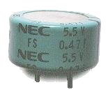 Super Capacitors - The Electric Double Layer capacitor is a real miracle piece of work. Capacitance is 0.47 Farad (470,000 uF). Despite the large capacitance value, itsphysical dimensions are relatively small. It has a diameter of 21 mm (almost an inch) and a height of 11 mm (1/2 inch).Like other electrolytics the super capacitor is also polarized so exercise caution in regards to the break-down voltage.Care must be taken when using this capacitor. It has such large capacitance that, without precautions, it would destroypart of a powersupply such as the bridge rectifier, volt regulators, or whatever because of the huge inrush current at charge. For a brief moment, this capacitor acts like a short circuit when the capacitor is charged. Protection circuitry is a must for this type.
 Polyester Film - This capacitor uses a thin polyesterfilm as a dielectric. Not as high a tolerance as polypropylene, but cheap, temperature stable, readily available, widely used. Tolerance is approx 5% to 10%. Can be quite large depending on capacity or rated voltage and so may not be suitable for all applications.
 Polypropylene - Mainly used when a higher tolerance is needed then polyester caps can offer. This polypropylene film is the dielectric.
Very little change in capacitance when these capacitors are used in applications within frequency range 100KHz. Tolerance is about 1%.
Very small values are available.
 Polystyrene - Is used as a dielectric. Constructed like a coil inside so not suitable for high frequency applications. Well used in filter circuits or timing applications using a couple hundred KHz or less. Electrodes may be reddish of color because of copper leaf used or silver when aluminum foil is used for electrodes.
 Metalized Polyester Film - Dielectric made of Polyester or DuPont trade name "Mylar". Good quality, low drift, temperature stable. Because the electrodes are thin they can be made very very small. Good all-round capacitor.
 Epoxy - Manufactured using an epoxy dipped polymers as a protective coating. Widely available, stable, cheap. Can be quite large depending on capacity or rated voltage and so may not be suitable for all applications.
 Ceramic - Constructed with materials such as titanium acidbarium for dielectric. Internally these capacitors are not constructed as a coil, so they are well suited for use inhigh frequency applications. Typically used to by-pass high frequency signals to ground. They are shaped like a disk, available in very small capacitance values and very small sizes. Together with the electrolytics the most widely available and used capacitor around. Comes in very small size and value, very cheap, reliable. Subject to drifting depending on ambient temperature. NPO types are the temperature stable types. They are identified by a black stripe on top.
 Multilayer Ceramic - Dielectric is made up of many layers. Small in size, very good temperature stability, excellent frequency stable characteristics. Used in applications to filter or bypass the high frequency to ground. They don't have a polarity. *Multilayer caps suffer fromhigh-Q internal (parallel) resonances - generally in the VHF range. The CK05 style 0.1uF/50V caps for exampleresonate around 30MHz. The effect of this resonance is effectively no apparent capacitance near the resonant frequency.
As with all ceramic capacitors, be careful bending the legs or spreading them apart to close to the disc body or they may get damaged.
 Silver-Mica - Mica is used as a dielectric. Used in resonance circuits, frequency filters, and military RF applications.
Highly stable, good temperature coefficient, excellent for endurance because of their frequency characteristics, no large values, high voltage types available, can be expensive but worth the extra dimes.
 Adjustable Capacitors - Also called trimmer capacitors or variable capacitors. It uses ceramic or plastic as a dielectric.
Most of them are color coded to easily recognize their tunable size. The ceramic type has the value printed on them. Colors are: yellow (5pF), blue (7pF), white (10pF), green (30pF), brown (60pf). There are a couple more colors likered, beige, and purple which are not listed here. Anyways, you get the idea...
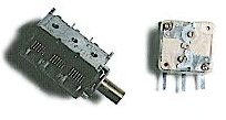 Tuning or 'air-core' capacitors.
They use the surrounding air as a dielectric. I have seen these variable capacitor types of incredible dimensions, especiallythe older ones. Amazing it all worked. Mostly used in radio and radar equipment. This type usually have more (air) capacitors combined (ganged) and so when the adjustment axel is turned, the capacitance of all of them changes simultaneously. The one on the right has a polyester film as a dielectric constant and combines two independent capacitors plus included is a trimmer cap, one for each side.
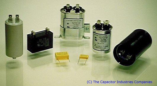
Combining Capacitors & Formula's:
Is it possible to combine capacitors to get to a certain value like we do with resistors? Certainly! Check below how go about it.
Capacitors in Parallel
 Capacitors connected in parallel, which is the most desirable, have their capacitance added together, which is just the opposite of parallel resistors. It is an excellent way of increasing the total storage capacity of an electric charge:
Ctotal = C1 + C2 + C3
Keep in mind that only the total capacitance changes, not the supplied voltage. Every single capacitor willsee the same voltage, no matter what. Be careful not to exceed the specified voltage on the capacitors when combining them all with different voltage ratings, or they may explode. Example: say you have three capacitors with voltages of 16V, 25V, and 50V. The voltage must not exceed the lowest voltage, in this case the 16V one. As a matterof fact, and a rule-of-thumb, always choose a capacitor which is twice the supplied input voltage. Example: If the input voltage is 12V you would select a 24V type (in real life 25V).
Capacitors in Series

Again, just the opposite way of calculating resistors. Multiple capacitors connected in series with each other will have the total capacitance lower than the lowest single value capacitor in that circuit. Not the preferred method but acceptable.
For a regular two capacitor series combo use this simple formula:
If you have two identical capacitors in series the formula is simplicity itself:
| microFarads (µF) | nanoFarads (nF) | picoFarads (pF) | ||
| 0.000001µF | = | 0.001nF | = | 1pF |
| 0.00001µF | = | 0.01nF | = | 10pF |
| 0.0001µF | = | 0.1nF | = | 100pF |
| 0.001µF | = | 1nF | = | 1000pF |
| 0.01µF | = | 10nF | = | 10,000pF |
| 0.1µF | = | 100nF | = | 100,000pF |
| 1µF | = | 1000nF | = | 1,000,000pF |
| 10µF | = | 10,000nF | = | 10,000,000pF |
| 100µF | = | 100,000nF | = | 100,000,000pF |
Table 1. Capacitance Conversion
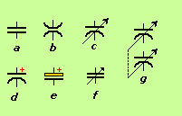 Capacitors in Schematics:
