Automatic water level controller circuit project
This is simple automatic water level controller
circuit. It will make you more comfortable Because it
enables open – close water pump automatically. When full of water, was ordered
off the water. But When levels gradually reduced To
the required, Then turned on fully the water. So We do
not have to worry about overflow and water out anymore.
The working principle.
As Figure 1 show working of circuit. In begin states when without water on a
bucket. Both transistor Q1 and Q2 will not works. Because the
base of both transistors not triggered from the common point. Which
still connect positive voltage through R1.

Figure 1 Simple automatic water level controller circuit
And this result to both transistors no
conduction. So current through R5 and D1 to trigger base of Q3, cause Q3
conducts current cause the transistor Q4 also works.
When Q4 conducts current, LED1 will get a direct
bias so glow, and relay-RY1 will pull in to contact continuously a water pump
with the AC-line 220 volts until water to low level (L) cause it as conductor
of electricity to base of Q1 get bias and conduct current at collector so have
voltage like ground.
But Q3 and Q4 exist voltage at collector so
there are voltage same the positive supply, the
current will flow through D1 to trigger base of transistor-Q3, so begin cycle
working new again.
How to builds
Because this project is a small and uses less
equipment so easy to build you can assemble them on universal PCB. Or will make
the PCB as Figure 2 (I am sorry for no copper layout). You need to put all
parts in the correct position, and matches terminal according to Figure 3.

Figure 2 The PCB
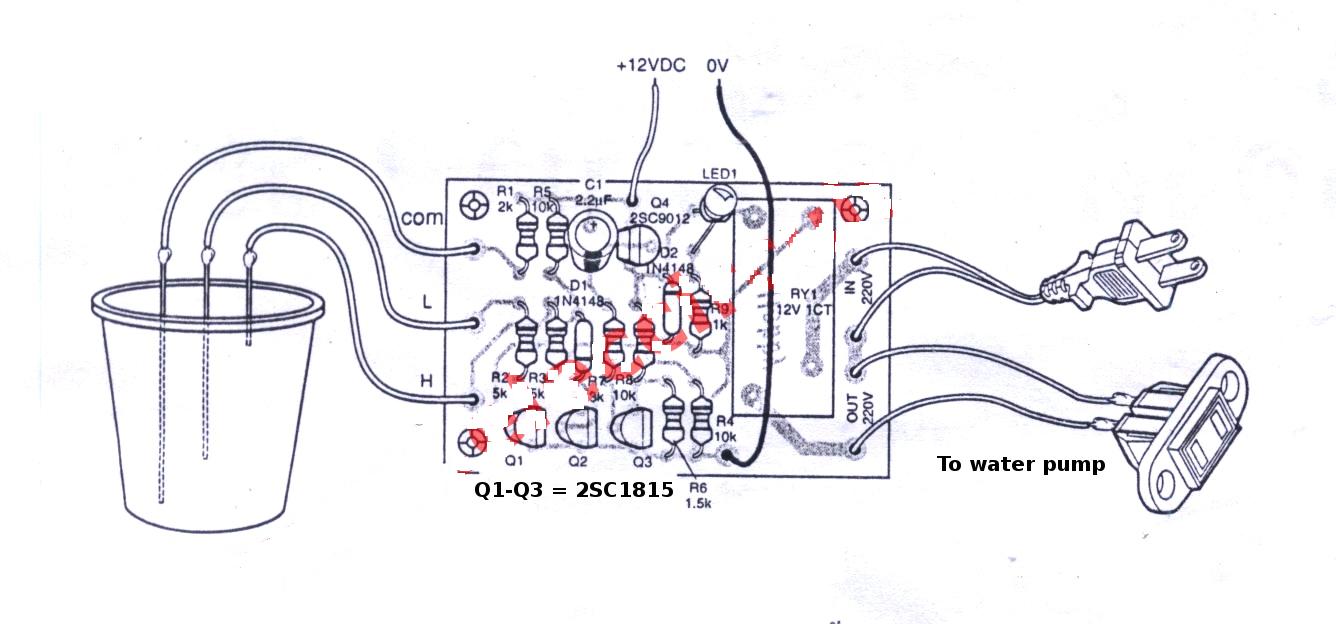
Figure 3 The components layout.
The external wires should larger size In particular 220 volts to load power should withstand a
minimum of 600 watts.
The external 12V power supply adapter can be
used from anywhere, but must be able to supply up to 300mA.
In real deployment must bring them mount in the
box neatly and securely. Because the circuit is the voltage AC 220 volts in the
PCB which will be harm easily. Put it in a box must be steel or plastic. But must be durable.
Testing
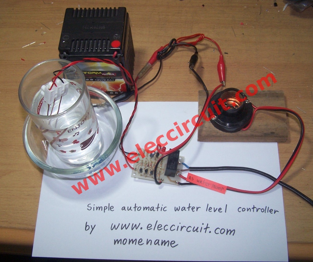
Figure 4 completly this project ready to test.
Remember, in testing circuit, do not connected
input and output to AC220V to this project, because may be danger while test
them.
Just connected DC 12 volts as power supply to
positive or +12V point and negative to 0V point. If not constitute any part of
an error, the result follows.
Firstly, when apply a 12V power supply in to
circuit. The LED1 will glow and relay will work. Then when we connect “H” and
“COM” point together. Next the LED1 will go out and relay will stop working
take “H” point out of “COM” point so cause LED1 will glow and relay pull in
again.
Secondly, short “L” and “COM” terminal, LED1
will glow and relay still working. Then short “H” to “COM” another one point.
Now all three terminals are connected to each end. As a result, the relay stops
working and LED1 goes off. When removing the terminal “H” out now relay will
not function and LED1 will not glow. When removable terminal
“L” out of the terminal “COM” now relay with LED1 light up.
As video below I am testing this project.
The Parts list
1.Q1-Q3______2SC1815 or 2SC1740 NPN transistors or similar___= 3 pcs.
2.Q4_________CS9012_PNP transistor or similar____ = 1
pcs.
3.D1,D2______1N4148 ___200V 75V 150mA Diodes ___= 2
pcs.
4.LED1_____As you like_______________ = 1 pcs.
5.R1_______2K 0.25W resistors_______ = 1 pcs.
6.R2,R3____5K___”_______”___________ = 2 pcs.
7.R4,R5,R8_10K__”_______”___________ = 3 pcs.
8.R6______1.5K__”_______”___________ = 1 pcs.
9.R7______3K____”_______”___________ = 1 pcs.
10.R9_____1K____”_______”___________ = 1 pcs.
11.C1_____2.2uF__25V___Electrolytic capacitor___= 1
pcs.
12.RY1____12V-1C 3A current relay_______= 1 pcs.
13.Wires,PCB, and others.
Application.
Take three line to connected to “L” “H” and “COM”
terminal will be a general copper wire and cut them as level you need but do
not short-circuited. We may install it into the pond or water tank.
Note: Do not use a point detector in oil or hazardous chemicals. Because it may
be a spark of the wire may cause explosion.