SLA = Sealed Lead Acid
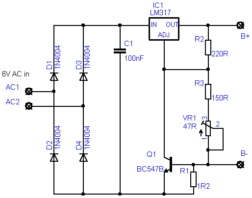
Schematic of the charger
| |
Single Cell SLA Charger
This charger is only meant for single cells of the lead/acid variety.
It can be used for cells with a capacity of up to around 10Ah if R1 is changed accordingly.
SLAs should be charged with a current of from 10% to 30% of their rated capacity (in Ah or mAh)
The circuit should never be left connected to a cell while the (mains) power is off, as this will drain the battery and could possibly damage the charger.
Wrong cell polarity will damage the charger.
These two issues could be solved by adding some bits 'n' bobs, but it is my understanding, that most people tends to go for the simpler/cheaper circuit, so I left that out.
Set the charging voltage, without a cell connected, for 2V35.
Charge only at or around room temperature (20-25°C).
|
|
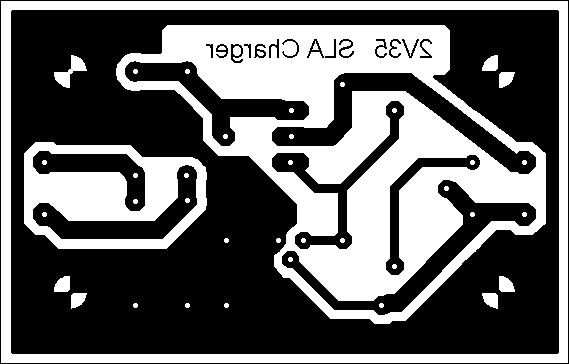
PCB Lay Out
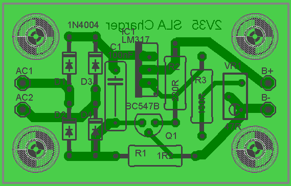
Component Overlay
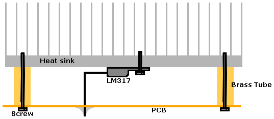
How to heat sink
Bill of materials
|
R1 | | 1R2 0.5W* |
R2 | | 220R |
R3 | | 150R |
VR1 | | 47R |
C1 | | 100nF |
D1-D4 | | 1N4001* |
Q1 | | BC547B* |
IC1 | | LM317T |
|
* Notes
D1-D4 can be any diode capable of 1A+ and Q1 can be just about any small signal NPN transistor
R1 could be selected for other charge currents:
|
| |
| | Charge | | Cell Capacity |
R1 | |
| | Current mA | | to charge (aH) |
4R7 | | 1/4W | | 130-150 | | 380-1,500 |
3R9 | | 1/4W | | 150-180 | | 460-1,800 |
3R3 | | 1/4W | | 180-210 | | 550-2,100 |
2R7 | | 1/4W | | 220-260 | | 670-2,600 |
2R2 | | 1/4W | | 270-320 | | 820-3,200 |
1R8 | | 1/3W | | 330-390 | | 1,000-3,900 |
1R5 | | 1/3W | | 400-470 | | 1,200-4,700 |
1R2 | | 1/2W | | 500-580 | | 1,500-5,800 |
1R0 | | 1/2W | | 600-700 | | 1,800-7,000 |
0R82 | | 1W | | 700-900 | | 2,200-8,500 |
0R68 | | 1W | | 900-1,000 | | 2,600-10,300 |
|
|
|