LM317T Variable Voltage Regulator
The LM317T is a adjustable 3 terminal positive voltage regulator capable of supplying in excess of 1.5 amps over an output range of 1.25 to 37 volts. The device also has built in current limiting and thermal shutdown which makes it essentially blow-out proof.
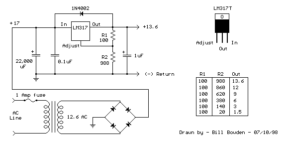
Output voltage is set by two resistors R1 and R2 connected as shown below. The voltage across R1 is a constant 1.25 volts and the adjustment terminal current is less than 100uA. The output voltage can be closely approximated from Vout=1.25 * (1+(R2/R1)) which ignores the adjustment terminal current but will be close if the current through R1 and R2 is many times greater. A minimum load of about 10mA is required, so the value for R1 can be selected to drop 1.25 volts at 10mA or 120 ohms. Something less than 120 ohms can be used to insure the minimum current is greater than 10mA. The example below shows a LM317 used as 13.6 volt regulator. The 988 ohm resistor for R2 can be obtained with a standard 910 and 75 ohm in series.
When power is shut off to the regulator the output voltage should fall faster than the input. In case it doesn't, a diode can be connected across the input/output terminals to protect the regulator from possible reverse voltages. A 1uF tantalum or 25uF electrolytic capacitor across the output improves transient response and a small 0.1uF tantalum capacitor is recommended across the input if the regulator is located an appreciable distance from the power supply filter. The power transformer should be large enough so that the regulator input voltage remains 3 volts above the output at full load, or 16.6 volts for a 13.6 volt output.
LM317T Voltage Regulator with Pass Transistor
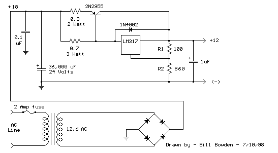
The LM317T output current can be increased by using an additional power transistor to share a portion of the total current. The amount of current sharing is established with a resistor placed in series with the 317 input and a resistor placed in series with the emitter of the pass transistor. In the figure below, the pass transistor will start conducting when the LM317 current reaches about 1 amp, due to the voltage drop across the 0.7 ohm resistor. Current limiting occurs at about 2 amps for the LM317 which will drop about 1.4 volts across the 0.7 ohm resistor and produce a 700 millivolt drop across the 0.3 ohm emitter resistor. Thus the total current is limited to about 2+ (.7/.3) = 4.3 amps. The input voltage will need to be about 5.5 volts greater than the output at full load and heat dissipation at full load would be about 23 watts, so a fairly large heat sink may be needed for both the regulator and pass transistor. The filter capacitor size can be approximated from C=IT/E where I is the current, T is the half cycle time (8.33 mS at 60 Hertz), and E is the fall in voltage that will occur during one half cycle. To keep the ripple voltage below 1 volt at 4.3 amps, a 36,000 uF or greater filter capacitor is needed. The power transformer should be large enough so that the peak input voltage to the regulator remains 5.5 volts above the output at full load, or 17.5 volts for a 12 volt output. This allows for a 3 volt drop across the regulator, plus a 1.5 volt drop across the series resistor (0.7 ohm), and 1 volt of ripple produced by the filter capacitor. A larger filter capacitor will reduce the input requirements, but not much.
High Current Regulated Supply

Simple Adjustable Voltage Source
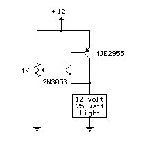
A simple but less efficient methode of controlling a DC voltage is to use a voltage divider and transistor emitter follower configuration. The figure below illustrates using a 1K pot to set the base voltage of a medium power NPN transistor. The collector of the NPN feeds the base of a larger PNP power transistor which supplies most of the current to the load. The output voltage will be about 0.7 volts below the voltage of the wiper of the 1K pot so the output can be adjusted from 0 to the full supply voltage minus 0.7 volts. Using two transistors provides a current gain of around 1000 or more so that only a couple milliamps of current is drawn from the voltage divider to supply a couple amps of current at the output. Note that this circuit is much less efficient than the 555 timer dimmer circuit using a variabe duty cycle switching approach. In the figure below, the 25 watt/ 12 volt lamp draws about 2 amps at 12 volts and 1 amp at 3 volts so that the power lost when the lamp is dim is around (12-3 volts * 1 amp) = 9 watts. A fairly large heat sink is required to prevent the PNP power transistor from overheating. The power consumed by the lamp will be only (3 volts * 1 amp) = 3 watts which gives us an efficiency factor of only 25% when the lamp is dimmed. The advantage of the circuit is simplicity, and also that it doesn't generate any RF interference as a switching regulator does. The circuit can be used as a voltage regulator if the input voltage remains constant, but it will not compensate for changes at the input as the LM317 does.
2 Cell Lithium Ion Charger
The charger operates by supplying a short current pulse through a series resistor and then monitoring the battery voltage to determine if another pulse is required. The current can be adjusted by changing the series resistor or adjusting the input voltage. When the battery is low, the current pulses are spaced close together so that a somewhat constant current is present. As the batteries reach full charge, the pulses are spaced farther apart and the full charge condition is indicated by the LED blinking at a slower rate.
A TL431, band gap voltage reference (2.5 volts) is used on pin 6 of the comparator so that the comparator output will switch low, triggering the 555 timer when the voltage at pin 7 is less than 2.5 volts. The 555 output turns on the 2 transistors and the batteries charge for about 30 milliseconds. When the charge pulse ends, the battery voltage is measured and divided down by the combination 20K, 8.2K and 620 ohm resistors so that when the battery voltage reaches 8.2 volts, the input at pin 7 of the comparator will rise slightly above 2.5 volts and the circuit will stop charging.
The circuit could be used to charge other types of batteries such as Ni-Cad, NiMh or lead acid, but the shut-off voltage will need to be adjusted by changing the 8.2K and 620 ohm resistors so that the input to the comparator remains at 2.5 volts when the terminal battery voltage is reached.
For example, to charge a 6 volt lead acid battery to a limit of 7 volts, the current through the 20K resistor will be (7-2.5)/ 20K = 225 microamps. This means the combination of the other 2 resistors (8.2K and 620) must be R=E/I = 2.5/ 225 uA = 11,111 ohms. But this is not a standard value, so you could use a 10K in series with a 1.1K, or some other values that total 11.11K
Be careful not to overcharge the batteries. I would recommend using a large capacitor in place of the battery to test the circuit and verify it shuts off at the correct voltage. 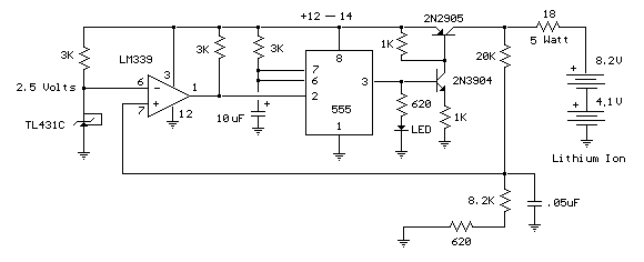
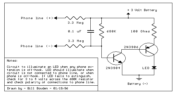
Telephone In-Use Indicator
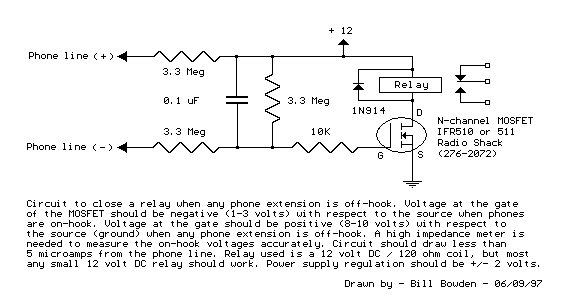
Telephone In-Use Relay Controller
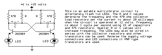
Astable Multivibrator
