This circuit does the exact opposite of what most of this type of changeover switches attempt to do. Usually a changeover switch is used with two PCs and one keyboard. This version however makes it possible to operate
one PC with two keyboards.
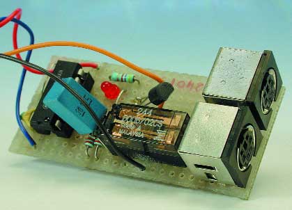
K1 is connected to the PC for this purpose while K2 and K3 are connected to two keyboards. The data outputs of the keyboards are high in the idle state. As soon as a key is pressed the keyboard will serially transmit the data. The data line will now also be low from time to time.
This low level is detected and remembered by the flip-flop circuit around IC1. If the signal originates from K3, the output on pin 6 will be high. Transistor T1 will conduct via resistor R5, which causes the relay to activate.
The signals on K3 are then connected straight through to plug K1. This situation will persist until a signal on the data line of K2 is transmitted. In that case the flip-flop will reverse and pin 6 will be low. The signal at resistor R5 will no longer cause transistor T1 to conduct and the relay will be in the rest position. The signals at connector K2 are now connected to plug K1. The
LEDs D1 and D2 indicate which keyboard is connected to the PC. The changeover of the signals via the relay is relatively slow, so the first keystroke is not properly transmitted to the PC. This means that when changing over the first keystroke will always be lost. Also take into account that when the PC is first switched on, the state of the flip-flop is random, so it is not clear which keyboard is initially connected to the PC.